
The intellectual result of O4 takes the form of two sets of interactive, online laboratory exercises that allow remote examination of the properties of real measurement sensors using real measuring equipment.
Overview
Two didactic measurement and control systems have been developed, one of which is intended for the implementation of experiments on sensors of electrical quantities – current sensors, and the other for the implementation of experiments on sensors of non-electrical quantities – linear displacement sensors.
The current sensor testing system allows you to test the static and dynamic properties of miniature current transformers and hall sensors with open and closed feedback loops, as well as test them in sample application systems. These types of sensors are often used to measure currents in electrical and power electronic systems. The system allows for the implementation of full programs of two laboratory exercises entitled Transformer input circuits of electronic measuring transducers and Hallotron current sensors, which are implemented in a traditional way in the Laboratory of Transducers and Measurement Systems of the Institute of Metrology, Electronics and Computer Science (IMEI) of the University of Zielona Góra (UZ).
The system designed for testing linear displacement sensors allows testing the static properties of transformer sensors (LVDT) and optical reflective sensors with analog and digital output. The system will allow you to perform a program of two laboratory exercises entitled Transformer linear displacement sensors and Optical sensors, which are carried out in a traditional way in the aforementioned Laboratory of Transmitters and Measurement Systems IMEI UZ.
The measurement and control systems use autonomous measuring equipment equipped with communication interfaces, a multifunctional Analog Discovery 2 (AD2) system and a set of relay keys allowing for remote selection of sensors for testing and measurement systems for these sensors.
System for testing current sensors.
Figure 1 shows the simplified structure of the system for testing current sensors.
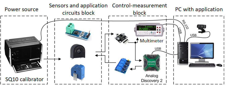
Fig.1. Structure of the system for testing current sensors
Its main elements are: a power source, a block of tested sensors and application systems, a measurement and control block, a computer with an application that supports the system that cooperates with the camera and is connected to the Internet. The power source in the system is a universal calibrator type SQ10. Three commercially available sensors are provided for testing in the system: TA 100 – transformer current sensor, ACS 712-05 – hall current sensor with an open feedback loop, LTS-6-NP – hall current sensor with closed feedback loop. The system also allows you to test two application systems of the ACS 712-05 sensor presented in the sensor data note, these are the peak current detector and the system increasing the sensitivity of the sensor’s voltage output.
Fig. 2 shows a view of the physical implementation of the system (station) for testing current sensors.
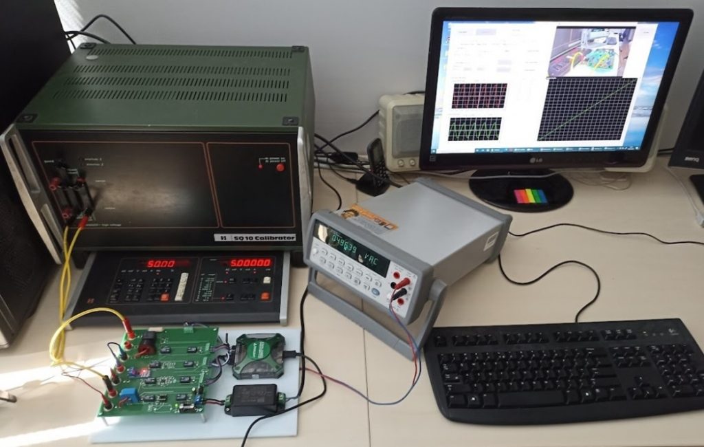
Fig.2. View of the system for testing current sensors
Linear displacement sensor testing system
Figure 3 shows the simplified structure of the system for testing linear displacement sensors.
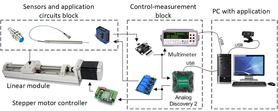
Fig.3. Structure of the system for testing linear displacement sensors
Its main elements are: a linear module with a stepper motor, a block of tested displacement sensors and application systems, a measurement and control block, a computer (connected to the Internet) with a camera and an application managing the system. The system tests LVDT sensors of PTx30 and PIz20 types, an optical sensor with an analog output of FT20RA-60-F-K4 type and an optical sensor with a digital output of LJ30A3-15-Z-CY type.
The sensor block also includes a set of voltage sources and a dedicated measuring amplifier for LVDT WG06 sensors. These systems allow you to test LVDT sensors at various power parameters and with dedicated conditioning systems. The linear module with stepper motor is designed to move: moving elements of LVDT displacement sensors (cores), a reflective surface for an optical sensor and a metal surface detected by an inductive proximity sensor.
Fig. 4 shows a view of the physical implementation of the system (station) for testing displacement sensors.
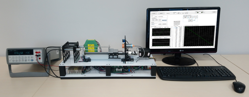
Fig.4. View of the system for testing displacement sensors
Local system support
Both systems are supported by software applications designed in the LabWindows/CVI environment, which have similar functions and a similar graphical interface. Each application performs the following functions:
- system configuration – choice of language version, sensor for testing, application system for the sensor, sensor power source, measuring device (AD2 or multimeter),
- system calibration – checking the correct operation of the power source or positioning the linear guide,
- measurements – selection of the measuring task and measurement mode (manual, automatic),
- presentation of measurement results – current measurement results, tabular summary, chart,
- archiving results – saving results to a file in CSV format.
Fig. 5 and Fig. 6 show the view of application windows controlling two systems. In the windows of these applications you can see the settings of input parameters of the tested sensors, the waveforms of input and output signals, summaries of measurement results in tabular form and in the form of a graph. You can also see a window containing the camera image or a block diagram of the system when the camera is not available.
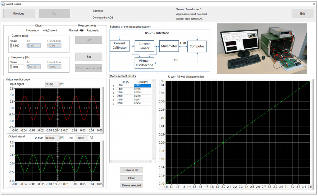
Fig.5. Window of the application controlling the system for testing current sensors
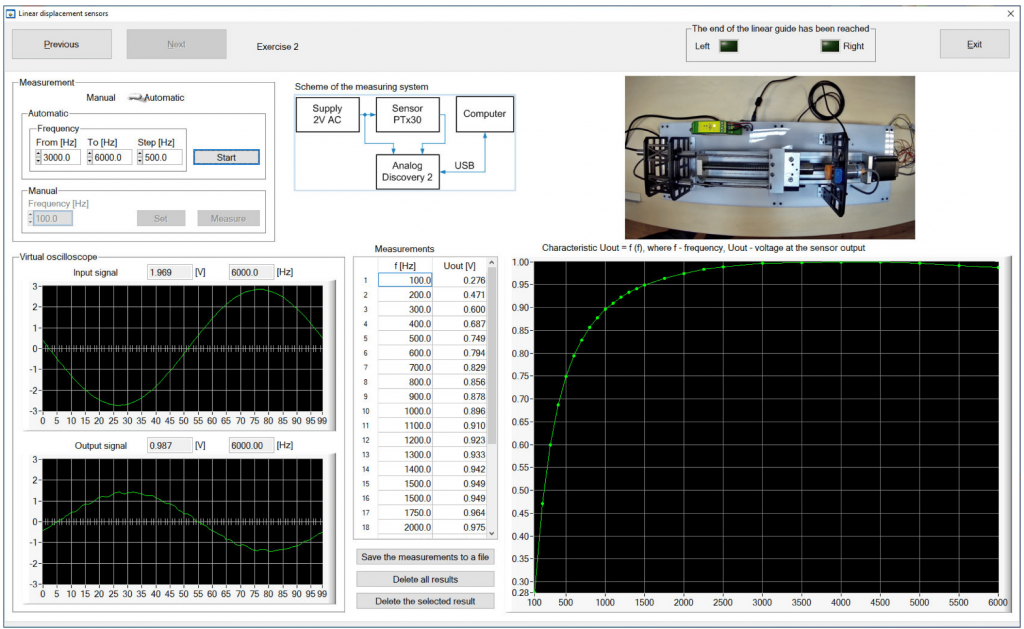
Fig.6. Window of the application controlling the system for testing linear displacement sensors
Remote system operation
Made systems can be operated remotely using the Chrome browser and the remote desktop technique provided by the Chrome Remote Desktop browser add-on. This technique provides the remote user with a view of the computer screen to which the measurement and control system is connected and thus allows for full operation of the application controlling the system in the same way as for local operation. Detailed information on remote access to the systems can be obtained via e-mail of the Institute of Metrology, Electronics and Computer Science of the University of Zielona Góra: sekretariat(at)imei. uz.zgora.pl.