
General description
The result of O2 output’s operation is a remote platform for the power electronics laboratory, which allows you to test a set of basic power electronics converters using a simple network interface (web browser or dedicated communication software).
Power electronics, dealing with the processing and quality of electrical energy, is one of the key branches of the electrical industry. Energy conversion is based on switching power electronic (semiconductor) elements. A simplified analysis of such systems is possible on the basis of electrical circuits (simulators). Many centers have developed simulation systems for power electronics for students’ needs. However, such a system does not allow for testing of systems operating in a real system, in particular the impact of parasitic elements and dynamic elements (e.g. the impact of inertial elements on the operation of the system).
Structure of the system
The subject of work as part of the O2 result was to connect a physical power electronics laboratory with a digital platform allowing for remote activation of these systems and online monitoring of responses to various types of operating states. The result was developed by the project leader – the Silesian University of Technology, which used the existing concept of the power electronics laboratory for this purpose, developing new sets of converters adapted to communication both in terms of setting and reading parameters remotely. The concept of the laboratory operation is presented in Fig. O2.1 in the form of a functional diagram.
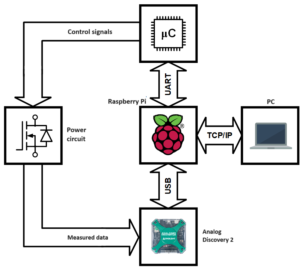
Fig. 1. Structure of the system
The most important element from the educational point of view is the power electronic converter. For the needs of the laboratory, a modular converter was designed, consisting of three elements: a passive input circuit, a passive output circuit and an active power electronic system consisting of four transistors or thyristors connected in the structure of a 3-phase H-bridge (containing 6 semiconductor elements). The connection diagram of a single module with transistors is shown in Fig. O2.2.
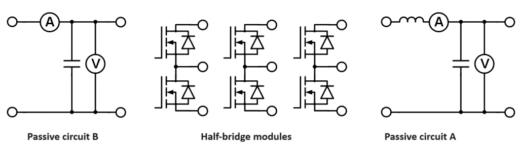
Fig. 2. Universal power electronics converter module, a) diagram, b) photo of a single half-bridge of the active system, c) photo of the passive input system
Range of exercises and structure of converters
Six converter sets were made for the laboratory, allowing six different laboratory exercises to be carried out in parallel (for a group of students). It is possible to carry out the following laboratory exercises:
- BUCK type DC/DC regulator,
- BOOST type DC/DC regulator,
- DC/DC regulator with power factor compensation PFC BOOST,
- Series resonant bridge inverter,
- 1-phase voltage inverter,
- 3-phase voltage inverter,
- 1-phase AC voltage regulator,
- 3-phase alternating voltage regulator,
- 3-phase diode rectifier,
- 3-phase thyristor rectifier.
Appropriate connections are made to obtain the appropriate converter (in the case of stationary classes, the connections can be made by students, while in the case of remote classes, the connections are made by the teacher). Examples of connection diagrams for DC/DC BUCK and BOOST regulators are shown in Fig. 3, and the appearance of the complete laboratory stand is shown in Fig. 4.
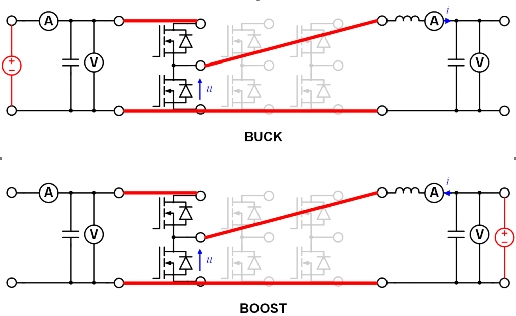
Fig. 3. Structure of circuits of DC/DC BUCK and BOOST
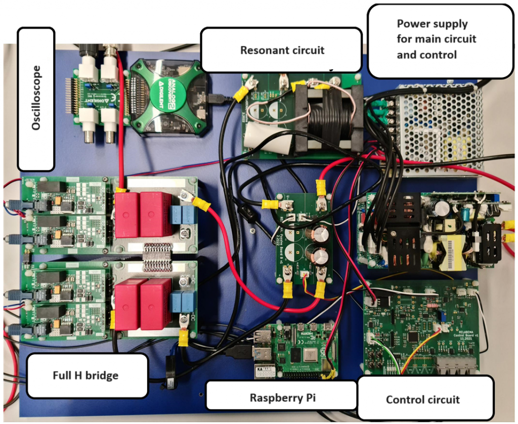
Fig. 4. Completed test bench for examination of power electronic converter
The manner of converter examination
The converter is controlled via a Raspberry PI microcomputer and a dedicated application developed in Python, while measurement acquisition is performed via an Analog Discovery 2 digital oscilloscope and a dedicated Waveforms application. Both access to the control application and to measurement acquisition is possible for a remote participant via an Internet communicator (the ZOOM platform is recommended in this case), which allows the remote computer to be controlled. The appearance of the control application for the resonant inverter and an example measurement course obtained with a digital oscilloscope are shown in Fig. 5. The appearance of the application may vary depending on the converter.
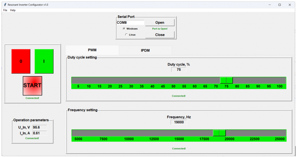
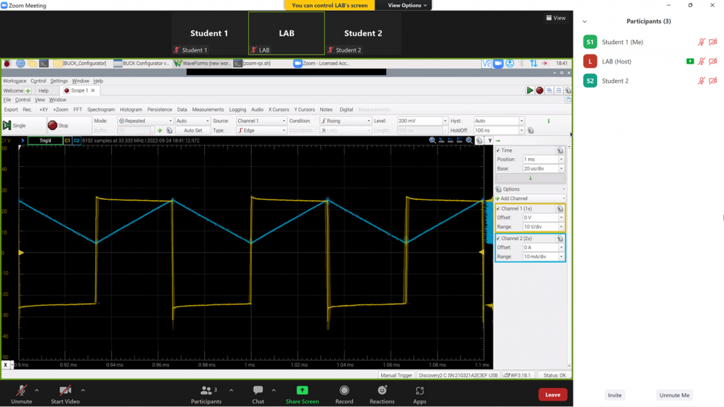
Fig. 5. Remote interface for setting parameters and data acquisition available via the ZOOM application
The substantive scope of individual exercises is usually determined by the instructors. Example descriptions of exercises can be found, among others, in the literature, e.g. [1], and additional materials can be found at http://kener.elektr.polsl.pl/energo.php. If you are interested in taking advantage of the laboratory’s offer, please contact the project leader or staff of the Department of Power Electronics, Electric Drive and Robotics of the Silesian University of Technology at <re5(at)polsl.pl>.
[1]. B. Grzesik [red.]: Energoelektronika – ćwiczenia laboratoryjne, Wydawnictwo Politechniki Śląskiej, Gliwice 2001